.lst in the folder E:\Training\Training Module No.1 Adjustment of Traverses\Training Exercises
Parcel "Main Traverse/" 15-Mar-2012 15:53:58
Original Dimensions Shown
From Bearing Distance Pt Easting Northing Radius ArcDist
1 200.000 500.000
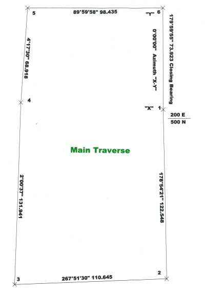
1 178 54 21 122.548 2 202.340 377.474
2 267 51 30 110.645 3 91.772 373.339
3 2 00 37 131.941 4 96.401 505.199
4 4 17 30 68.918 5 101.558 573.924
5 89 59 58 98.435 6 199.993 573.925
6 179 59 55 73.923 1 200.000 500.000
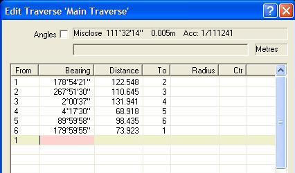
Misclose 111°32'14" 0.005m Acc: 1/111241
Make sure it is saved in the Current Survey directory and that you select when requested to amend or replace.
At this stage depending on your angular close which has been determined by your field readings you may want to adjust the bearings before you run the Bowditch adjustment. In our example you have a misclose of only 5"
In your calc book, paste in two copies of the initial misclose.
On the second copy adjust your bearings by writing the adjusted bearings in pen.
In the edit traverse window you can now overwrite the bearings with your adjusted bearings, Right click and [Calc Misclose] again
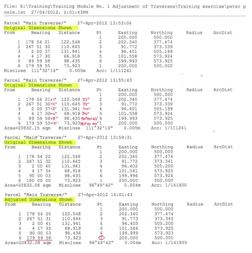
Print Traverse again. Use the "Append" option and not "Replace" when printing and paste in your calc book. Hopefully your misclose has been decreased. Do NOT tick the "Print Adjusted Dimensions Box"
Now it is time to apply the Bowditch adjustment by Right Click and choose the option
Note the the bearings and distances displayed, your raw traverse remain displayed unchanged however adjusted points have been written to the main file and show on the main screen.
To print the adjusted bearings and distances right click and tick the "Print Adjusted Dimensions box". Print, Append and Paste in Calc book.
Close the edit Traverse screen and return to main screen.
Here you will find your loop traverse adjusted and joined by a traverse string.
If you require a certain traverse line orientated to a fixed starting azimuth ie "X"-"Y", you can rotate around your initial known point. In this case swing your job +0?00'02" around Point 1
Select on the Tool Bar
Select
Select , the default is All Points, All Layers which is fine if you have only traverse points in your file. If you have other existing points in the file you will have to select the range of new traverse points.
Select tick box
Key in the rotation angle +0?.00'02"
Key in rotation point, Point 1
Select
Check that you have rotated your traverse correctly so the "X-Y" starting azimuth in our case is 0?00'00"
To adjust a traverse between two fixed points, you must key in the two fixed points in your job before you start and proceed as above.